CNC Router

Self-designed, 3D Printed, desktop-sized

Background

Around 2022, my high school robotics team purchased an entry level CNC router for about $7,000. Throughout the next few years, I spearheaded the project by teaching myself, and later others, how to run this new machine efficently and with good results. Applying this process to our robot build process significantly decreases our prototyping and manufactruring time along with increasing precision.

In Spring of 2025, I realized that I would soon be graduating and would no longer have access to one of these machines. This, along with my immense urge to have a larger and larger collection of cool toys... *cough* *cough* tools... led me to start designing and building my own, just a little be cheaper and thermore much smaller.

Current State

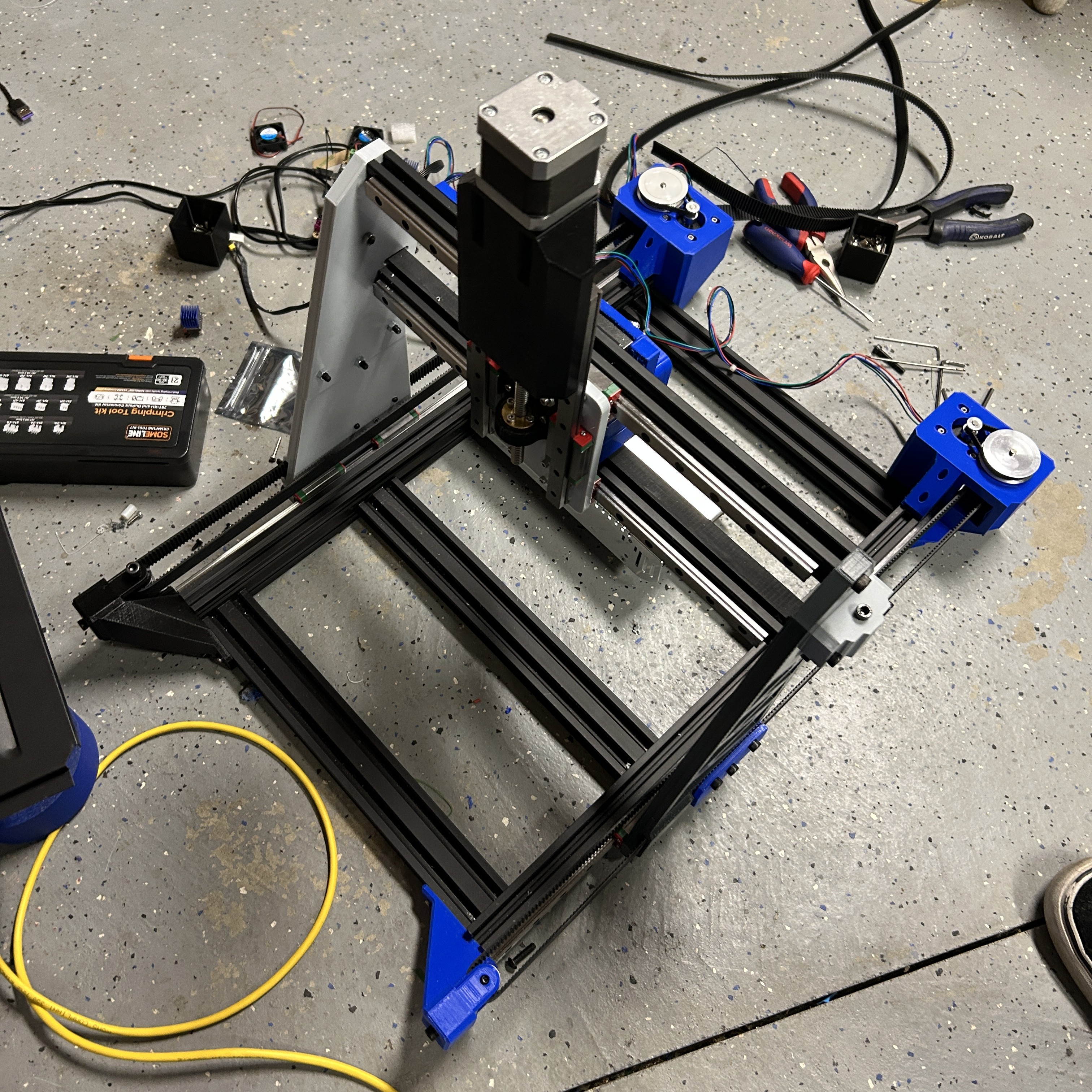
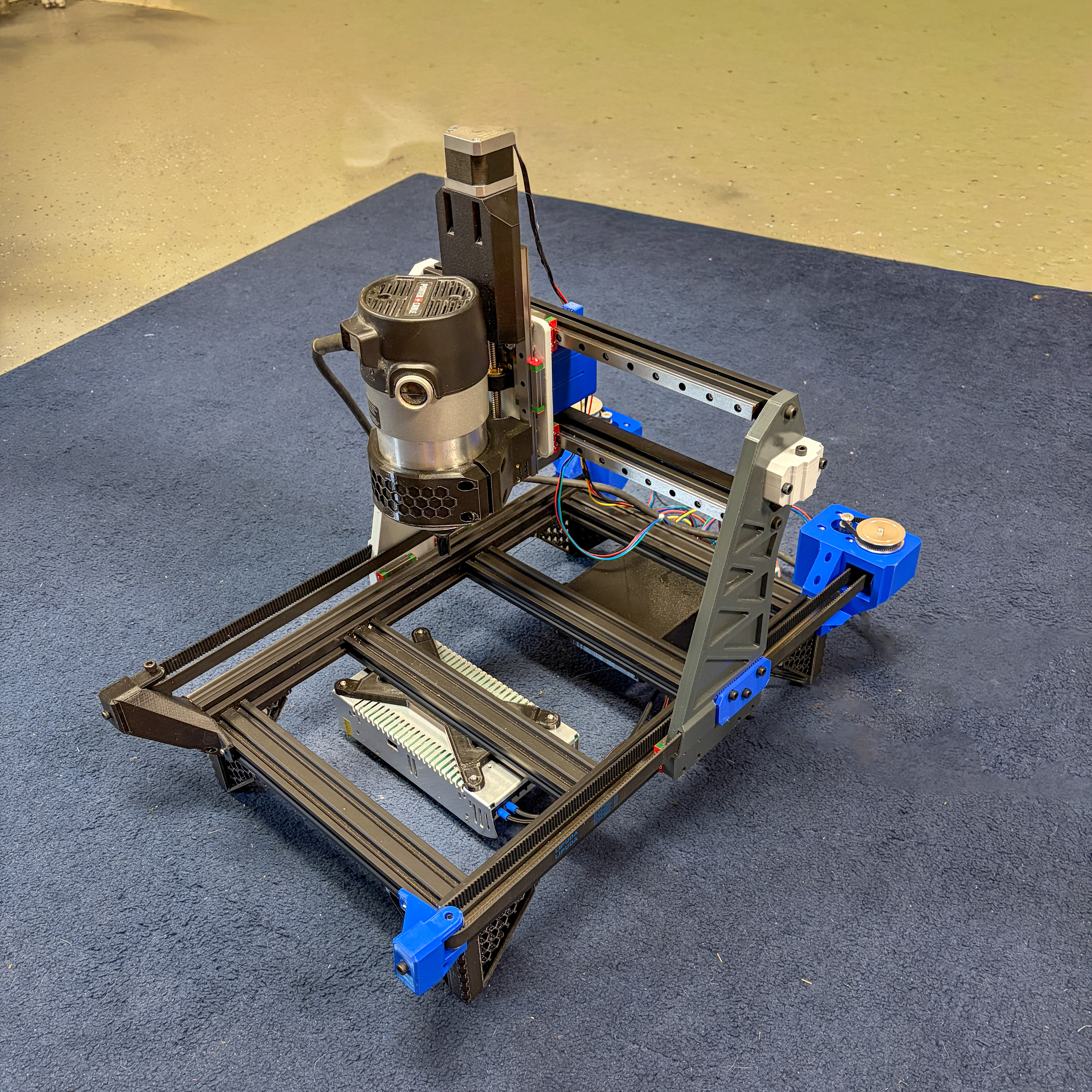
All axes (X,Y,Z) are moving and are somewhat calibrated.
It needs a few design revisions, specfically to the router mount.
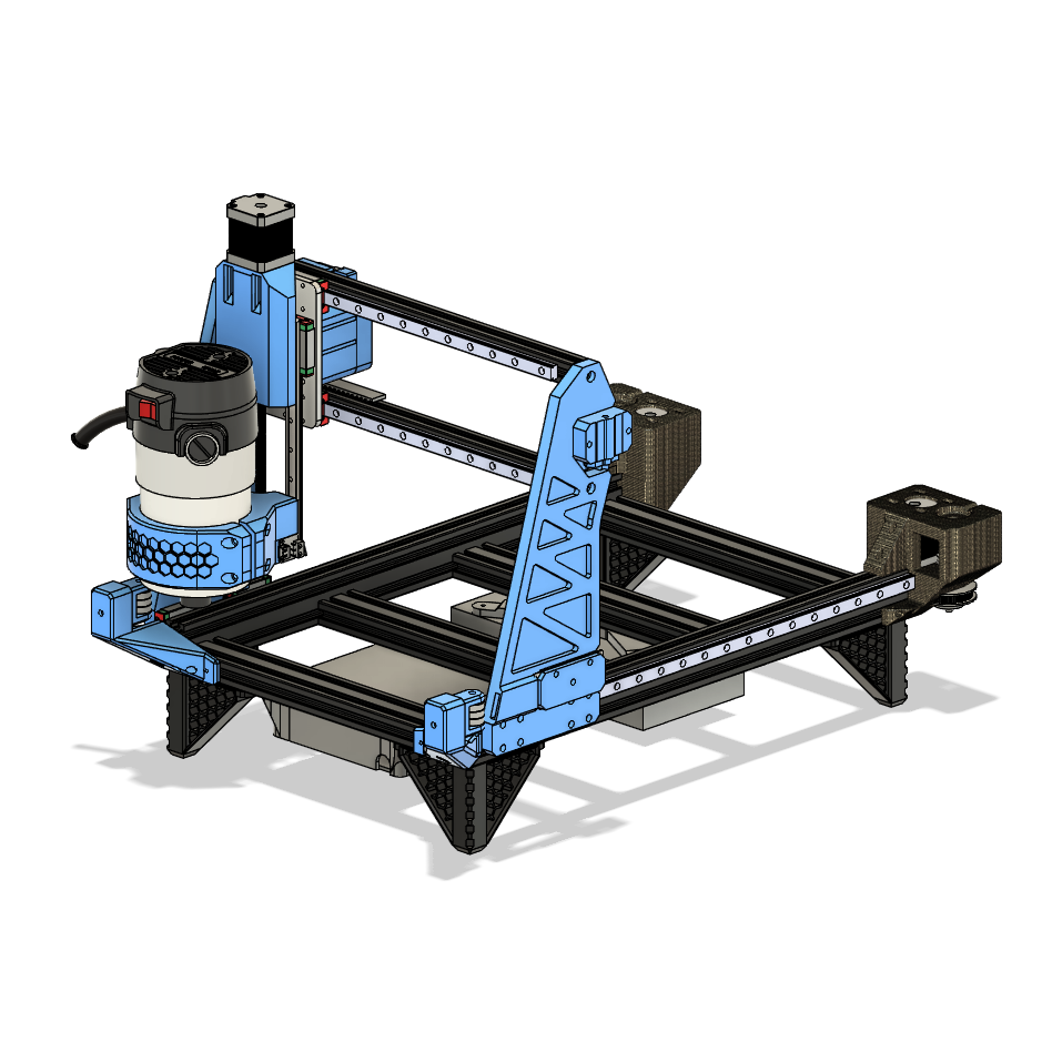
Next Step

Revise and reprint Router Mount, figure out endstops (physical and virtual), install spoil boards, test cuts!

Process

Below is a list of major milestones during this project with images. The top is the most recent.

Main Board Mount

- Designed Mount for the mother board with cble routing and cooling in mind
- Printed the mount
- Mounted the board and wired the components to the board.


Power Supply Mount

- Designed Mount for power supply
- Printed PSU mount
- Adjusted th moun to align with the holes
Lesson Learned - Don't trust dimensions in documentation of cheap chinese parts


Finished Y-Axis

- Redesigned tensioner at the front
- Printed new parts
- Assembled motor and stepdown belt
- Attached printed parts to frame
- Struggled to route main belt (might need to update design to make this easier)


Work in Progress

This page are still a work in progress.

More Information to come!


Gantry

- Cut 2020 aluminum extrusion to length
- Tapped the ends for M6 bolts
- Bolted the bars in place
- Attached the liner rails to the from face of the extrustion


y-axis Rails

- Attached linear rails to the side of the frame using M3s and t-nuts
- Attached 3d printed main gantry supports to linear rails


Frame

- Cut Aluminum extrusion to length
- Drilled holes in side bars for bolts
- Tapped ends of inner bars
- Assembled the frame


Design & CAD

In the last few months of my senior year of high school, I researched and designed with any free time I had. I was heavily interested in getting the idea into a form that could actually work. After about a month, I was happy with the design enough to order the parts.